
An exploded view can make a simple product instantly understandable. It can also invent a hidden mechanism that the product does not contain. The difference starts with the part list you give the image model and the claims you attach to the result.
Draft a product-part composition · Download the component review sheet
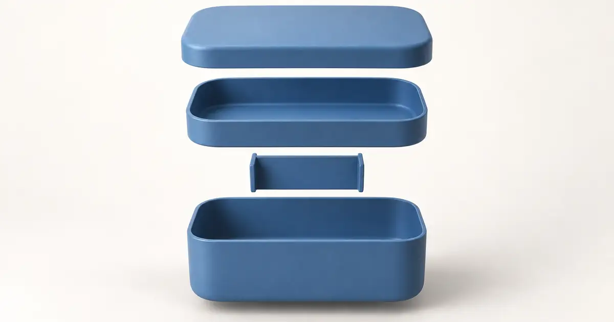
Checked September 14, 2026. The bento-box example is an invented four-part design for explaining the workflow. It is not an engineering drawing or a claim about a real product. The hero is AI-generated.
Decide whether the image explains or documents
A conceptual exploded view can communicate an idea: a lunch box has separate compartments, a sandwich contains visible ingredients, or a product concept consists of several layers. A technical exploded view identifies real components and their relationships. The second job requires accurate source information that a single exterior photo cannot provide.
Onshape's exploded-view documentation starts from an assembly and moves its existing components through recorded steps. That is a different evidence base from asking an image model to imagine what is inside a sealed object. Use a CAD-derived view for instructions where actual component order, dimensions, or attachment matters.
For marketing, an illustration can still be useful. Label it according to what it is and avoid claims the source cannot support. A polished image of a battery, motor, and cooling system does not establish that those parts exist in a photographed appliance.
Start with a component inventory
Our original example is a simple blue bento box with four conceptual components: a lid, an upper tray, a removable divider, and a lower container. The divider belongs in the lower container. We will separate the components vertically for visibility, not claim that the drawing specifies an assembly procedure.
| ID | Component | Visible characteristics | Relationship |
|---|---|---|---|
| A | Lid | Plain rounded rectangle | Covers the upper tray |
| B | Upper tray | Shallow container with a continuous rim | Sits above the lower container |
| C | Divider | One removable flat partition | Fits inside the lower container |
| D | Lower container | Deeper rounded rectangle | Holds the divider |
For a real product, replace this illustrative table with an approved inventory. Photograph accessible parts separately, obtain the manufacturer's artwork, or ask the product owner for a verified view. Mark unknown components as unknown. Do not silently fill the list with plausible-looking screws or seals.
Count removable components and visible subassemblies consistently. If the lid contains a permanently bonded insert, decide whether the image should show it as one assembly or two components. The illustration should answer the viewer's question, not maximize the number of floating pieces.
Choose a separation direction that reveals the relationships
Vertical separation works for the bento example because the main containers stack. Keep the lid and trays in a shared perspective, then place the divider where its destination is understandable. If a component slides sideways in the real product, a small lateral offset may explain it more clearly than forcing every part onto one axis.
Spacing is a communication choice. Too little separation hides edges; too much makes the pieces look unrelated. Begin with enough room to distinguish each silhouette and add a caption or connector only where it resolves ambiguity. The same spacing does not need to work for both a tall divider and a shallow lid.
Use consistent camera perspective. If the lower container shows its left interior wall, the upper tray should not suddenly reveal the opposite side from an incompatible angle. This mismatch can make parts appear as if they could never fit together, even when their individual shapes are plausible.
Write a bounded image brief
Use the brief in Image Lab. If the selected model supports references, provide the approved component images. Ask for the relationship and the visual constraints, then inspect the result against the inventory. Naming exactly four parts is useful direction; it does not make the count a guaranteed model constraint.
For real product artwork, keep the source component images available at full resolution. If a generated component loses a distinguishing edge, a manual layout made from those approved images may be more accurate and faster than repeated regeneration.
Review count, geometry, and meaning in that order
Count: identify A, B, C, and D in the output. Look for a second lid, an extra tray rim interpreted as another part, or a divider that has become two pieces. If you cannot map the image to the inventory, fix that before color or lighting.
Geometry: compare compatible dimensions and visible edges. Does the divider appear to fit within the lower container? Do the lid and tray share a plausible outline? A perspective image does not provide measurement accuracy, but obvious incompatibilities are still visible.
Meaning: ask what a viewer will infer. A floating gasket can imply a seal. A glowing internal layer can imply electronics. An arrow can imply a prescribed assembly direction. Remove unsupported cues or label the image as a concept in a way that remains visible when it is reused.
Existing guides such as Masonry's exploded-view workflow already distinguish conceptual imagery from engineering truth. The component-by-component map adds a practical review artifact: another person can point to the exact part that is missing or inaccurate.
Add labels after the parts are right
Use real text in a design editor for labels, dimensions, and callouts. This keeps spelling, alignment, and later revisions under control. Place labels near the relevant component without crossing several other parts. If a label needs a long paragraph to explain where it points, simplify the composition.
Choose language that describes what is verified. “Removable divider” is appropriate only when that is a confirmed property of the actual item. Avoid turning a visual treatment into a claim such as leakproof, insulated, medical-grade, or impact-resistant without separate support.
For a small ecommerce image, reduce the number of labels and inspect it at card size. Detailed technical lettering that is readable only at full resolution may add clutter without helping the shopper understand the product.
Animate the separation only when it improves the explanation
A short animation can reveal the relationship between the assembled form and separated parts. Begin from approved images, keep the camera restrained, and move components along clear paths. Review whether the number and shape of pieces remain stable throughout the motion.
One common failure is interpenetration: a tray passes through another solid component instead of moving around it. Another is a component dissolving at the midpoint and reappearing at the endpoint. A correct opening and closing frame do not make the intervening motion accurate.
Video Lab can explore a conceptual motion treatment from a supported reference input. For a precise assembly animation, use the verified 3D assembly or conventional animation controls. The appropriate tool depends on whether the audience needs a visual idea or a reliable mechanical explanation.
Package the image so its context survives reuse
Save the approved component list, source references, final image, and caption together. If you produce a concept, include that label in the deliverable context rather than only in an internal note. A teammate may otherwise reuse the image as if it were product documentation.
Before delivery, ask someone unfamiliar with the project to name the parts and explain how they relate. Their answer is a useful comprehension check. If they identify a fifth component or misunderstand where the divider belongs, revise the image before adding more polish.
Frequently asked questions
Can AI infer accurate internal parts from one exterior photo?
No reliable inference is guaranteed. Use a verified part inventory, component references, or CAD when real internal structure matters.
Can I use an AI exploded view in assembly instructions?
Only after the relevant geometry and procedure have been independently verified. A CAD-derived or technical illustration is a stronger starting point for that job.
Should all parts be spaced equally?
Not necessarily. Space them so their shapes and relationships are clear. Different component sizes may need different gaps.
What is the first useful QuestStudio step?
Draft a bounded illustrative arrangement in Image Lab using the approved component references where supported. Check the part count and relationships before animating it.